Whatever you might not know about Plasma Cutting and wish to be informed about!
Plasma Cutting characteristics
Plasma is defined as "... a gas in which a certain portion of the particles are ionized. The presence of a large number of charge carriers makes the plasma electrically conductive so that it responds strongly to electromagnetic fields. Plasma, therefore, has properties quite unlike those of solids, liquids, or gases and is considered to be a distinct state of matter..."
For arc cutting, we take advantage of the fact that Plasma is electrically conductive. Being so hot, not even its own atoms can remain unaffected and they get ionized, that is they emit free electrons which can then freely move from one atom to the other and the atoms themselves are left with a positive charge. Positevely and negatively charged particles give plasma its electro-conductive property.
What do we have here? We have an excessively hot gas mass than can also conduct electricity. The idea of forming a jet of this gassy mass to attack and melt metals was only one step ahead.
For this idea to be realised, some kind of a "plasma gun" should be produced. It should be enough heat resistant to contain the plasma and designed in a way to be able to target it at the metal to be cut. Because no material would remain intact at 22000 degrees Celcius, there was only one way out: Design a "gun" in such a way that the ionised gas be "enveloped" in a much cooler gassy "container", the parts involved provided with constant cooling and make sure they be made of a material of the highest possible melting point. Additionally, it should constrict the plasma jet so that its thermal energy would concentrate on a small area of the target material, for better results.
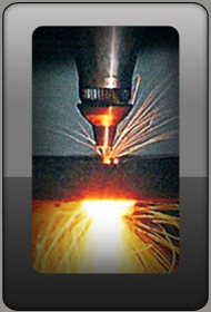
A plasma torch uses a copper alloy nozzle to constrict the ionized gas stream to focus the energy to a small cross section.
The high velocity gas jet ejected through the nozzle transfers electric current to the plate we wish to cut which is melted and the molten material is driven away by the very plasma jet.
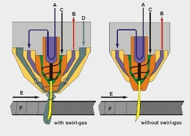
In our drawing to the right please see a Plasma torch design with or without Swirl Gas, about which we explain right underneath: A. Coolant entry, B. Coolant exit, C. Plasma Gas, D. Swirl Gas, E. Cutting direction and F. Cut surface.
Swirl Gas
The introduction of Swirl Gas technology assists cutting in many ways. To begin with, gas swirling helps cooling. The non-ionised atoms of the gas are heavier and cooler than the ionised ones and, when forced to swirl, are distributed on the outer layer of the swirling gas "column". This lower temperature layer protects the copper alloy nozzle. The higher the current, the greater the percentage of ionised atoms, so that the "ideal ratio" of 30% plasma, 70% cool gas gets higher, increasing the eating of the nozzle and reducing its cooling. Nozzles are designed and manufactured to function within a given range of current amperage.
 Swirl gas improves cut quality. If plasma jet is not swirling, both kerf sides would be bevelled, sometimes to an extent that makes work-pieces useless (please cheque drawing to the right: A. Straight gas flow, cut surface bevelled on both sides). By swirling the gas, the plasma jet is distibuted on one side evenly, therefore this cut surface is "square" (Figure to the right B. Swirled gas jet, square cut surface). If swirling direction is changed (clockwise instead of anti-clockwise), the square side changes diametrically. The swirling gas jet attacks one side of the sheet to be cut vertically in its full thickness. Cutting energy is distributed evenly over the full thickness of the work-sheet, resulting in a cut surface perpendicular to the one of the work-sheet. This is the cut edge to use; the one across the kerf is inclined at an angle of some 5 to 8 degrees.
Shield Gas introduction can further constrict the jet and cool the nozzle. This gas is injected in the plasma jet in the last stages of its flow through the torch, after it is ionised, at the nozzle tip.
 Plasma Arc initiation
There are three main parts inside a torch:
- The Electrode
- Gas or Swirl Controller (Baffle)
- The Nozzle
These parts are gradually worn during the cutting process and must be replaced; this is why they are called Consumables. In our photo to the left we see the Kjellberg PerCut 370.M Torch consumables (Right to Left: Electrode - Swirl Gas Controller - Nozzle). Torches of different makes, or even different torch types of the same manufacturer may look different, but they all necessarily include these three parts to do the job we have described. To cheque the configuration of your Torch consumables please look into your machine's manual.
The electrode is connected to the negative pole of the direct current generated by the Plasma Power Generator. The nozzle is connected to the positive pole, but is electrically isolated through an open relay.
When we give our system a Start input, the whole process is realised through the following stages:
- 1. The Main Plasma Power Connector activates placing a strong negative voltage on the Electrode
- 2. The Gas starts to flow to the torch and, as it flows through the Swirl Control, it starts swirling
- 3. The normally open contacts in the nozzle circuit close, connecting it to the positive pole of the generator
- 4. A high frequency generator creates a high-voltage and high-frequency potential between the electrode and the nozzle. This potential initiates a tiny arc between the afore-mentioned parts ionising the gas enveloping it
- 5. The creation of this ionised "pathway" induces starting of a bigger direct current arc between the electrode and the nozzle; this is what we usually call a Pilot Arc.
- 6. The Pilot Arc is driven outside the nozzle, blown forward by the gas stream, and it eventually comes in contact with the work-plate
- 7. The Main Arc is created when the Pilot Arc touches the plate, provided the latter is at the right distance. The nozzle relay opens and the nozzle is again isolated. Now all the prerequisites for the tranferred Arc have been established
- 8. The Main Arc gets more powerful because the current is increased after the nozzle has been put out of the circuit by relay opening
Double Arc: Conditions causing it
Double Arc is created when the nozzle remains connected to the power generator, and this can happen under very special conditions. As previously described, the nozzle should stay isolated from the cutting Arc circuit and only be connected to it during the Pilot Arc creation stage. In case it fails to disconnect and it carries the cutting high amperage, it gets damaged.
Double Arcing can be caused by:
- Standing Pierce. The torch must be positioned to such a distance from the plate that the Pilot Arc has a chance to come in contact with it; otherwise the Main Arc will fail to start. Molten metal slag, splashes towards all directions during the initial stages of piercing but, as the hollow becomes deeper, the jet blowing through the nozzle orifice is "reflected" upwards carrying slag against the very nozzle. If this slag comes to form a connecting "bridge" between the nozzle and the plate, being electrically conductive, it keeps the nozzle connected to the main Arc circuit even after the nozzle relay opens to isolate it. Such a malfunction could destroy the whole of the front end of the torch and not just the nozzle.
- Torch touching the plate. Thin material cutting. All systems of automatic torch positioning make use of some THC (Torch Height Control) method to determine the right distance between the nozzle tip and the work-plate. One such method is the "Touch and Retract" one. The torch is lowered slowly until it touches the plate lightly and etracts to the right height driven by the CNC automation. If the sensor fails to accurately judge the distance or anything else goes wrong, the torch may stay in contact with the plate because of its springing up or warping. In this case the nozzle will stay in the cutting amperage circuit and it will get damaged.
- Pilot Arc Malfunction. Sometimes the nozzle relay fails to isolate it. This may be due to a relay short circuit or some shorted resistor. Also in this case the nozzle has to face a much higher amperage than it is designed for and it is damaged.
Double Arc: Prevention techniques
Double Arc mainly occurs during the piercing process. There follow some methods to help avoid it:
- Creep Torch move. The machine is configured so that the torch is in slow motion during the Main Arc Transfer stage. Torch velocity is approximately 5% to 10% of the normal cutting velocity, and this slowing down only takes place for a short time. Pierce slag cannot accummulate on the nozzle, since the latter is moving, drastically reducing the chances for Double Arcing.
- Slow rising of the torch during piercing. If we prefer to do standing pierce,
 during the main arc initiation, the torch slowly rises away from the work-sheet, and spatter cannot easily damage the nozzle. The torch continues to move upwards for the pre-configured time period and then, when the machine starts moving the cutting head at normal velocity, it moves down to the normal cutting height.
 - Initial Standing pierce with the torch positioned higher than normal. With the torch distanced from the work-sheet longer than normally, it gets more difficult for spatter to build a "bridge" between the nozzle and the sheet, drastically reducing Double Arcing chances. This last preventive method is the least effective of the three.
Plasma Cutting Process parametres
Maximum productivity, maximum cut quality and maximum consumables life depend on a series of important cutting parametres, all of which should be carefully considered and controlled to balance.
Α. Gas purity
Gas purity is a variable of fundamental importance as far as high cut quality and long consumables life are concerned. Minimum purity required for Nitrogen is 99,995% and for Oxygen 99,5%. If purity levels are below the minima recommended, the following malfunctions can occur:
- The arc may fail to penetrate thin materials regardless the amperage
- Excessively shortened Electrode longevity
- Uneven cut quality, depending on the gas contamination degree.
- When cutting with N2, we get a thin blackish layer on the nozzle orifice and the electrode; the higher the contamination degree, the thicker the residue layer. When the gas is pure, the electrode and the nozzle have a somehow sand-blasted appearance
Β. Gas pressure and Flow velocity
Each nozzle is designed and manufactured to perform at an optimal amperage matching a given gas pressure and flow. Raising the pressure results in shortening the elecrode's life duration. In this case the electrode tungsten core develops a drilled appearance. If we work with Nitrogen, we may have difficulty with starting the torch. If the torch fails to start, we may notice that the Pilot Arc comes sputtering. This sort of problems occur when there is too high gas pressure. With too low gas flow we get double arcs.
 C. Kerf
Kerf is the width of the material removed by the cutting process. Three major variables are involved in Kerf forming:
- a. Cutting Speed (Feed Rate). When cutting speed is higher (keeping the rest of the parametres constant), kerf gets narrower. It will keep getting narrower, up to the point that loss of arc will occur (Drawing to the right: A. Narrow Kerf, failed cut, B. Wider Kerf, Cut accomplished).
- b. Cutting Amperage. If we increase the Cutting current, keeping the rest of the parametres constant, the kerf gets wider. If we keep on increasing the amperage, the kerf will continue getting wider until the nozzle is destroyed. Decreasing the amperage, the kerf gets narrower and the cut angle gets more positive until arc penetration fails.
- c. Standoff. Standoff is the distance between the nozzle tip and the work-sheet surface while the cutting job is in progress, after the piercing stage is over. Most advanced systems make use of some automatic capacitive feedback sensor. By increasing the arc voltage, standoff is increased and kerf gets wider. Excessive standoff values result in loss of cutting ability. By decreasing standoff, the kerf gets narrower and eventually cutting ability is likewise lost.
D. The Arc Voltage
The Arc voltage depends on a multitude of parametres:
 a. Cutting Current Amperage
- b. The diametre of the nozzle orifice
- c. Gas Flow
- d. Cutting Height
- e. Cutting Velocity
The gases generally needed to perform a plasma cutting job are of three kinds: A start gas, a cut gas and a shield gas. In some cases an extra shield gas may be needed. There are some parametres that should be taken into consideration when we plan a cutting job:
- Type and thickness of the material
- Cutting duration
- Cut quality and
- Production costs
The choice of the gases to work with depends on the specific job or the torch type. Generally speaking, different cutting results are achieved with different combinations of Oxygen, Nitrogen, Air, Methane and H-35 (a combination of 65% argon - 35% hydrogen); Argon is also used for engraving jobs.
For detailed info please refer to your machine's manual.