IDA CONTROL
Automation Robotics
PANAGIOTIS M.PIKIS AND CO.
243 Agiou Dimitriou St.,
17342 Agios Dimitrios, Athens,Greece
Phone: +30 210 982 1806
Fax: +30 210 983 2431
Email: info@idacontrol.com
Articles

Whatever you might not know about Laser Cutting and wish to be informed about!
Laser Cutting - General Info
Laser is a beam of monochromatic coherent radiation. This means that it comes from a source (called a Resonator) that produces (emits) radiation (light or even in the invisible spectrum) of in-step waves of identical frequency, phase, and polarization. Laser light is generally a narrow-wavelength light; yet, there are lasers that emit a broad spectrum of light, or emit different wavelengths of light simultaneously.
We shall not go into details explaining the way the laser beam is produced; it is perhaps enough to know that the initially produced radiation (Light of a specific wavelength) passes through tubes filled with some “gain medium” and is amplified (increases in power); surrounding mirrors ensure that most of the light makes many passes through the gain medium, being amplified repeatedly. Part of the light that is between the mirrors (that is, within the cavity) passes through the partially transparent mirror and escapes as the beam of Laser light.
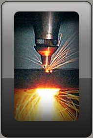
This extremely powerful beam, focussed by a system of mirrors and lenses, and assisted by the high-velocity flow of some kind of gas surrounding it, is delivered through the cutting nozzle and can melt away the material it attacks.
Advantages of Laser Cutting
Laser technology has the following advantages: - High accuracy: It is the only technology to cut or mark intricate drawings
- Excellent cut quality wherever it can be applied
- Small kerf
- High processing speed
- Compared to other thermal cutting processes, very narrow heat-affected zone
- Minimum deformation of the cut sheet because of the very low level of heat applied
- Many different types of materials (i.e. not exclusively metallic ones) can be cut
- No need to change tools when cutting and marking
- It can cut intricate shapes, very small holes and bevelled surfaces
- No contact between the focussing head and the job and therefore no force applied to the work-sheet
- Real-time control of the laser power over a wide range of amperage (1-100%) enables a power reduction on tight curves and pulse piercing
 - Laser cutting leaves a very thin and easily removable oxidation layer
- High-pressure laser cutting with nitrogen enables oxide-free cutting
Principles of Laser Cutting
A diagram of a laser beam delivery system is shown below, consisting of:
1. CO 2 laser resonator, where the excitation of carbon atoms produces single wavelength light emission.
2. Depolarising mirror
3 and 4. Telescope optics
5. beam benders
6. Focussing lens
7. Cutting head
8. Cutting nozzle
9. Work material sheet
The focussing device consists of either a zinc-selenide lens or a parabolic mirror which brings the laser beam to a focus at a single point. Depending on the laser beam power, a power density of more than 107 W/cm2 is achieved at the focus point. 
The focal length gives the distance between the focal point and the focussing optics.
The focal point is positioned above, on or below the material surface according to the requirements of the material (See below: Focussing point depending the material). The power density heats up the material instantly, melting it and partially vapourizing it. The gas jet flowing through the cutting nozzle removes the molten mass away from the kerf.
The machine, CNC driven, moves the cutting head over the metal sheet following the pre-programmed pattern (G-Code), cutting the work-piece from the sheet.
Laser Cutting Methods
There are two main cutting methods, which depend on the type of the material to cut:
A) Fusion Cutting (high pressure cutting): - The material is fused by the energy of the laser beam
- The gas, in this case nitrogen at high pressure (10 to 20 bar), is used to blow away the molten material from the kerf
- The gas jet also protects the focussing optics from splashes
The presence of nitrogen protects the cut edges from oxidation and is mainly used with stainless steel, aluminium and their alloys.
B) Oxidation Cutting (laser torch cutting): - The material is heated by the laser beam to combustion temperature
- The gas, in this case oxygen at a medium pressure (0.4 to 5 bar), is used to oxidise the material and to drive the slag out of the kerf
- The gas also protects the focussing optics from splashes
- A large part of the energy for the cutting process is supplied by the exothermic reaction of the oxygen with the material
Cutting method B is the quickest one and is used for the cost-effective cutting of carbon steels. Laser Cutting: Parametres involved
Cut quality depends on the following variables: - A. Beam generation
- Laser power
- Pulse frequency
- B. Beam delivery
- Distance between the cutting nozzle and the work-piece
- Focal length of the focussing optics
- Focal position
- Cutting speed
- Acceleration
- C. Cutting gas configuration
- Type and pressure of cutting gas
- Diametre and type of nozzle
- D. Material characteristics
- Material Type
- Work-piece surface
- Work-piece shape
- Material thickness
- Work-piece support
Laser power
When deciding which laser power is best for the actual job or, more importanly, which system to purchase, we must have in mind that decisive factors are the type and surface of the material (metallic or not, thick or thin, its melting point, more reflective or less so, etc). Sometimes, when cutting "difficult" contours or tiny parts, a reduction in the laser power may be necessary to achieve high accuracy. In contrast a laser power of at least 1000 W is needed for cutting carbon steel thicker than 8mm (5/16”).
Pulse frequency
When cutting small contours or piercing it is recommended that we use reduced pulse frequency, adjusted to the specific task. When we do so while piercing, we say that we work in the ramp mode. Piercing can of course be done quickly at full laser power, but it can also be performed slowly using the so-called “ramp”. We do this by gradually increasing the laser output at the beginning of the piercing task, then keep it constant until the hole has been formed, and finally reducing it slowly again.
Type of gas - gas purity
The cutting gas to be used is mainly determined by the type of the material to be machined. Oxygen, for example, is only used when cutting metallic materials with oxide-free edges; used on any combustible material would set it on fire! As we have mentioned previously, oxygen inducts an exothermic combustion process forming a thin oxide layer on the cut surface.
With the laser torch cutting (Method B) of metallic materials the degree of purity of the applied oxygen is particularly important. Traces of nitrogen or humidity lead to the formation of burrs. This type of cutting gas contamination may be caused by bottle replacement and the connection of contaminated bottles.
Recommended oxygen purity: 99.95 % (3.5)
If oxygen with a purity of 99.5% (2.5) is used, the possible cutting speed is reduced by approximately 10%.
The quality of Nitrogen as cutting gas (N2) is also very important for the high pressure cutting of stainless steel. Even slight traces of oxygen lead to the formation of a fine oxide layer, which may render the job unacceptable.
Gas pressure
The material thickness of the work-piece must be matched to the pressure of the gas used. When torch cutting (B cutting method, Oxidation Cutting - laser torch cutting), thin metallic sheets are cut with a higher gas pressure than thicker materials. The gas pressure must be set very carefully, because the cut quality is affected by even slight changes in the oxygen pressure.
If the pressure is too low, the fluid slag remains adhered to the base material, forming a permanent burr or closing the kerf again. If the pressure is too high, the lower edges of the cut are burnt out, often destroying the work-piece.
In contrast with high pressure cutting, thicker work-pieces are cut at higher gas pressures.
Cutting nozzles and nozzle size
Manufacturers of consummables produce and sell different nozzles for different cutting jobs. For example, with high pressure cutting nozzles with a larger orifice are used than with standard cutting. Any deformation of the roundness of the nozzle orifice leads to directionally dependent cutting, due to the beam's eccentricity. In such cases, a consumables replacement is the only way to achieve acceptable cut quality, so, please, make sure you have enough consumables in store. Even if cut quality is negligibly affected (in the case of an orifice slightly larger than specified) gas consumption is considerably increased.
Nozzles with orifice of smaller diameter fail to produce clean and slag-free cuts, if they ever manage to cut the material. The slag remains attached to the bottom edge of the kerf and makes further machining obligatory.
Nozzle distance
The distance between the cutting nozzle and the surface to be cut is controlled by some type of THC (Torch Height Control), usually a capacitive one, so that no contact is made between them. Cut quality is decisively dependent on the nozzle distance: the smaller this distance, the better cut quality we achieve. At the same time, the risk of running into some kind of system crash, due to a collision (nozzle landing on the material surface), gets greater. So, it is advisable to try and keep a minimum distance of about 6.3 mm (0.024 in). While hole-piercing, nozzle distance is determined taking into consideration the type of hole-piercing and the sheet thickness.

Laser Focussing optics
The focussing optics cause the laser beam to be focussed into a single spot through the nozzle. The focussing optics may either be a zinc-selenide lens or a parabolic mirror.
1 = Laser beam
2 = Focussing lens
3 = Assist gas supply
4 = Cutting head nozzle
5 = Cutting direction
6 = Cut surface
7 = Work-sheet cross-section
8 = Melt layer
9 = Blow-out of molten mass
Focussing lens
Focussing lenses should be kept clean! A dirty focussing lens absorbs more laser radiated energy, heats up and deforms. A deformed lens changes its focal length and the focal position moves higher yielding worse cut quality. Please pay attention to the fact that, in the case of heavy contamination, the lens could be seriously damaged.
Lens deformation usually slows down cutting velocity and increases cutting duration; burrs start to form and build up and the kerf and surface roughness increase. If the problem is grave we may be unable to fully cut the work-piece. If we attempt to cut carbon steel we face the problem of cratering. Crater formation takes place regardless of the carbon content of the steel. Melting starts at the subsurface layer, resulting in the nucleation of small droplets which, under further heating, they boil and erupt through the surface. The liquid around these craters shrinks to fill up the cavity formed and, during the cooling process, leads to the formation of a funnel-like crater morphology.
Focal lengths
The Focal lengths of the lenses used are usually 12.7 mm (5 in) for thin materials and 19 mm (7.5 in) for thicker sheets. When we use 12.7 mm (5 in) optics the kerf is narrower compared to the 19 mm (7.5 in) optics, giving a higher energy density for the same laser power, resulting in slightly higher cutting speeds for the same material thickness / laser power combination. If mainly thin materials are cut, the 12.7 mm (5 in) optics are therefore to be recommended for reasons of economy.
The 19 mm (7.5 in) optics offer a greater maximum cutting thickness. The 19 mm (7.5 in) optics can be used to cut a large range of thicknesses, but it is more cost-effective to mainly use it for thicker materials.
 Focus position Focus position
The very process of cutting is due to overheating of the severing path; it is therefore understandable that we must position the focus of our system exactly where we wish to transfer the maximum of the laser energy. The more we are successful at this, the better the cut quality of the job. Speaking of laser-beam torch cutting of carbon steel, experience has shown that best results are achieved if we stick to the following rules:
a) Focus on the sheet surface (f=0) when sheet thicknesses are up to about 6 mm.
b) Focus above the sheet surface when sheet thicknesses are of 8 mm and over (f>0).
For high pressure cutting of stainless steel or aluminium we should position the focus in the very sheet (f<0), at about 2/3 of its thickness. The final conclusion is that we should change the focus position to match different material/thickness combinations.

Centering the beam through the nozzle:
The focussing lens must be set in such a way that the focussed laser beam be placed in the centre of the nozzle hole. A well focussed laser beam should at most be +0.05 mm (+0.002”) off centre with respect to the nozzle.
1 = Nozzle Orifice, 2 = Laser Beam
a is centred, b and c are not centred. With otherwise good cutting quality, a non-centred laser beam can lead to the cutting quality being dependent on direction. In the extreme case the cut is very good in one direction but in the other directions the material is not cleanly cut or even not parted.
With the torch cutting of carbon steel sparks can form on the surface of the sheet when cutting takes place in a direction opposed to the eccentricity.
Cutting speed
The cutting speed must be matched to the type and thickness of the work-piece. A speed which is too fast or too slow leads to increased roughness, burr formation and to large drag lines.
Acceleration
This is an equally important feature, and one that was of primary concern in the past; modern CNC equipment, though, takes hand of it automatically, so we need not worry!
Material
Composition of metals and the methods for their production influence their characteristics. Thermal conductivity and absorption, tension, reflectance, content in other substances are the most important. - Non-Ferrous metal sheets
- Aluminium: Limited ability to cut, because of its high reflectance and thermal conductivity. Additionally, cutting is dependent on the specific alloy. Cut quality is improved with higher alloying content. It can be cut to a thickness approx. 30% of the cutting thickness in the case of carbon steel with the same laser power.
- Copper and Brass: Likewise, they are of very high reflectance and thermal conductivity. Cutting thickness is less than the one achieved in aluminium, only 1mm for copper and 2mm for brass. Make sure you provide the operator with protective equipment against reflected radiation
- Silver and Gold: Practically impossible to laser cut.
- Iron and Steel sheets
Steel should be with low silicon, carbon and phosphorus contents. It should also be produced free of internal stresses. This makes the best metal to laser cut with high cut quality and very high cutting speed. If a high percentage of carbon content is present, the cut surface forms a thin layer of hard grey-blackish oxides. The cleaner the alloy, the easier it is to cut it.
- Non-metals
Cutting should be taken care of individually, depending on the special characteristics of the material: - Acryl Glass, PVC and Polyurethane offer good cut quality and high cutting speeds, but we should take special air filtering measures; their cutting could generally generate hazardous fumes.
- Leather, wood, cardboard and paper can be cut with high cut quality, only producing some discolouration since the cut surfaces get carbonised.
- Ceramics or Quartz can be cut with good results
- Glass can be cut, but special care must be taken to avoid forming of cracks due to high thermal concentration (and thermal expansion) locally./li>
Work-piece surface
Laser Cutting is mainly an optical phenomenon, and the laws of optics govern the whole process. It is also an aerodynamics process, with cutting gas flow also being susceptible to surface characteristics. Sheets with reflecting or deflecting surfaces should not be expected to be cut successfully. Dirty or processed surfaces may respond unexpectedly. Gas flow will be deflected by rough surfaces. Sheets covered with polyethylene film react, on condition, better when we try to cut them.
- Shiny Material Surfaces
They strongly reflect the laser beam; both cut quality and sheet thickness values are lower. For example, laser power of 1500W can cut 12mm (0.47 in) of mild steel but only 4mm (0.16 in) of pure aluminium.
- Sprayed and Painted Surfaces
Laser cutting is hindered by mill scale; both the laser beam and the cutting gas flow are adversely affected. Painted or plastic coated surfaces affect the cutting process.
- Warped or otherwise damaged surfaces
Rolling marks and grooves, stamps and cavities deflect or diffuse laser beams and gas flow. As expected, the thicker the sheet the acuter the problems. Increased cut surface roughness and prolonged cutting times are to be expected.
- Sand-blasted and abrasive grain processed surfaces
Sand grain deflects the focussed laser beam and hinders proper gas flow; the silicon content of sand causes additional problems. Surfaces with a rough texture can also create problems. In case they have solidified slag cutting quality is negatively affected, to the extent to suffer some machine crash, if anomalies are large enough.
- Surfaces with a layer of oil
Such cases are not affected and the cutting job can proceed normally. Slag adherence is impaired.
- Galvanised steel
Can be cut to a thickness of 3.2 mm (1/8 in). It is required that the galvanised layer is applied by electrolysis and is of approx. 8 μm layer thickness.
- Self-adhesive polyethylene coated sheets
Usually without problems up to 3.2 mm (1/8 in), provided the film is on the upper surface and it is not too thick (to approx. 100 μm).
Caution: Hazardous fumes may be produced when cutting plastic coated sheets.
Work-piece shape
Certain shapes of the work-piece, such as fine bridges, acute angles, or small holes (hole diameter smaller than sheet thickness) must be cut with reduced parameters:
- reduced laser power
- reduced cutting speed
- lower pulse frequency
Otherwise there is the risk that too much heat will be applied to the work-piece and parts of the shape will be burnt away.
Material thickness
As with Plasma Cutting, laser cutting material with greater thickness results in increased cut surface roughness. Cutting thicker sheets may take considerably longer than cutting thinner sheets of the same material and with the same laser power.
Work support table
The underside of the work-sheet, being in constant contact with the support table, does not always remain unaffected by the cutting process. This may lead to small grooves on it (please see photo to the right) and adherence of solidified splashes to the undersurface due to melting of the support bars. The very cutting process could also be interrupted if the torch comes to cut over the honeycomb support.
|
|